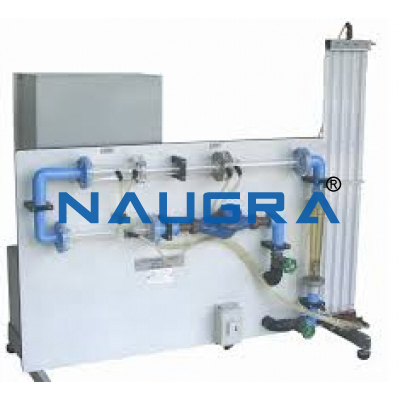
Industrial Flow Meters Trainer .
Industrial Flow Meters Trainer
- Principle Teaching Objectives
- Study of the implantation of the sensors.
- Calibration of the sensors.
- Determination of the characteristic curves of the sensors and their accuracy.
Functioing:
A centrifugal pump suck-up a non
compressible fluid (water) from a buffer tank; this fluid flow via an
adjusting membrane valve and a rotameter on two pipes on which are
mounted different flow sensors: an electromagnetic flowmeter, a vortex
flowmeter, a turbine flowmeter on one hand, and a venturi and a
diaphragm on the other hand (this two devices are linked to a
differential pressure sensor). The fluid flow in a closed loop and
return to the buffer tank.
Technical specifications
- A centrifugal pump
- A PVC tank
- A speed driver allowing
Flow meters
- 1 Venturi in Altuglass
- 1 Diaphragm in Altuglass
- 2 manometers in U and a differential pressure sensor
- 1 Rotameter
- 1 Electromagnetic flowmeter
- A tension is applied to the fluid that is captured by two electrodes and informs a converter of the fluid speed.
- 1 vortex flowmeter
- 1 turbine flowmeter
- A turbine with blades in plastic turns in relation with the flow
around a shaft. A magnet transmits this rotation to a Hall sensor
mounted outside of the case. Electronics linked to the sensor transforms
the frequency in instantaneous flow.
- The bench is presented on a stainless steel frame with aluminium nuts. The piping are made of PVC.
- The control cabinet include the control and the safety protection of
the pump, as well as the speed driver and the power supply for all
transmitters.
- The electronics of each flowmeter is local (on the flowmeter), the
display of the pressure sensor is deported on the electrical cabinet.
Options :
- We can propose on inquiry other flow meters configurations:
- Option 1 : Ultrasonic flowmeter
- Option 2 : Mass flowmeter
Essential requirements
- Power supply : 220 V mono 50 Hz – Power 0.37 kW
- Clean water : 4 bar, 20°C, for the tank filling

