- Workshop Tools and Workshop Machines India: buy@naugra.com

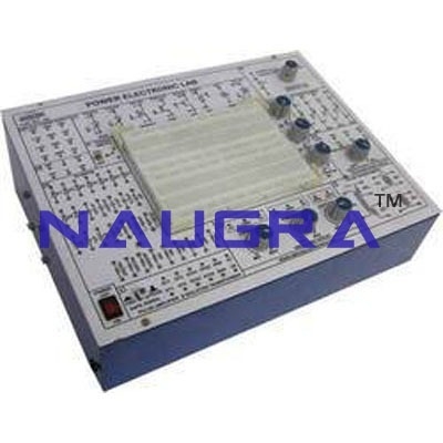
Electronic Circuit Lab .
The trainer should have a main experiment unit with the below components: DC Power Supply
-Fixed DC power supply: Voltage 5V, 12V ; Max. current output 0.3A; wth output overload protection
- Dual DC power supply: Voltage range 3V~ 18V, continuously adjustable 1A ; Max. current output 1A ; With output overload protection
AC Power Supply
- Voltage range 9V~0V~9V ; Max. current output 500 m A ; With output overload protection
Function Generator
Output waveform Sine triangle, square Output frequency 10~100KHz/4 settings ; Accuracy : ±5% of full scale value Output impedance : 50Ω ; output voltage : 18Vp-p (open loop) 9Vp-p (with 50Ω load
3 1/2 digital voltmeter/ammeter
-DC voltage range 2V 200V DC current range 200μA 2000mA
Analog Meters
(1) AC current : 0 ~ 100mA ~ 1A
(2) AC voltage : 0 ~ 15V
(3) DC current : 0 ~ 100mA ~ 1A
(4) DC voltage : 0 ~ 20V
Speaker
one 8Ω, 0.25W speaker with driver circuit
Variable Resistors
(1) 1KΩ, 0.25W variable resistor with 3 terminals (A,B,C)
(2) 10KΩ, 0.25W variable resistor with 3 terminals (A,B,C)
(3) 100KΩ, 0.25W variable resistor with 3 terminals (A,B,C)
(4) 1MΩ, 0.25W variable resistor with 3 terminals (A,B,C)
Breadboard
-1680 tie-point breadboard on top panel that can be easily put into and taken off
Experiment Modules
1. 17 experiments modules secured in a solid-body plastic housing
2. Each module to be equipped with an 8-bit DIP switch for fault simulation
3. Comprehensive experiment manual and instructor's manual. The trainer modules should be as follows:
- Diode, Clipper and Clamper Module
- Rectifier, Differential & Integrator Circuits
- Transistor Amplification Circuits
- Field Effect Transistor (FET) Circuits
- Multistage Amplification Circuits
- OTL Amplifier Circuit
- OCL Amplifier & Feedback Circuit
-Two Oscillator Circuit Modules
- Voltage Regulator Circuits
- Voltage Regulator & Amplitude Modulation (AM) Circuits
- Frequency Modulation (FM) & OP Amplifier Circuits
-Five OP-Amp Circuits modules
Experiments List
- Characteristics of Diodes: Silicon, Germanium, Zener, LED & Optical Diodes
- Clipping and Clamping Circuits with Diodes
- Rectifier Circuits
- Differential and Integrator Circuits
- Transistors: PNP transistor, NPN transistor
- Transistor Amplification Circuits
- Field Effect Transistors (FET)
- FET Amplification Circuits
- Multi - Stage Amplification Circuits
- Transistor Negative Feedback Circuits
- Transistor Positive Feedback Circuits
- Regulated Voltage /Constant Current Circuits
- Modulation and Demodulation
- OP-amps
- Basic Characteristics of OP Amplifier
- Basic Characteristics of OP Amplifier(1)-Negative Feedback
- Basic Characteristics of OP Amplifier(2)-Negative Feedback
- Basic Characteristics of OP Amplifier - Positive Feedback
