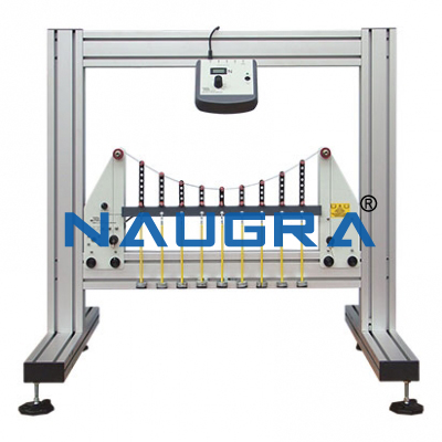
Forces On A Suspension Bridge .
Forces on a Suspension Bridge
Learning Objectives / Experiments of Forces on a Suspension Bridge
- Familiarisation with a suspension bridge
- under dead-weight
- under additional load
- under evenly distributed load
- under unevenly distributed point loads
- Calculation of the supporting cable force
- Comparison between calculated and measured values of the supporting cable force
- Observation of the effect of internal moments in the roadway under uneven load
- Load distribution between roadway support and supporting cable
Specification of Forces on a Suspension Bridge
- Investigation of a suspension bridge in various load cases
- Suspension bridge with 2 supporting cables and roadway
- Supporting cables with parabolic sag
- Hangers (vertical supporting cables) in the form of U-shaped shackles in graduated lengths
- Two-section roadway with central hinge
- Roadway can be loaded by additional weights
- Hinge in roadway indicates internal moments of roadway under uneven loading
- 4 graduated weight sets to measure the cable force in both supporting cables
- 2 supports with force gauge for the roadway
- Storage system to house the components
Technical Data of Forces on a Suspension Bridge
- Suspension bridge
- Span: approx. 1050mm
- Supporting cable sag: approx. 325mm
- Number of supporting cables: 2
- Shackles: 12, graduated lengths
- Dead-weight of roadway: 6N
- Support force measuring range: -50...+50N
Weight set
- 4x 1N (hangers), 16x 1N
- 16x 5N

