- Workshop Tools and Workshop Machines India: buy@naugra.com

Alignment Of Drives Shafts And Gears .
Technical Description of Alignment of Drives, Shafts and Gears
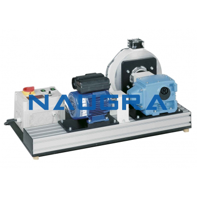
The units (shaft with journal bearings) and (combination gear units) are tested with unit. The assembled element system - journal bearing or gear unit - is mounted on the test bed. Here, the complete system is properly assembled, with particular regard to the alignment of the system components. A successfully completed assembly project can then be examined in operation with a formal final test. Parameters examined during test procedure are; running noise, heat generation, vibration or leakage. Includes a single-phase asynchronous motor drive, a magnetic particle brake with adjustable braking torque, and a rigid machine bed with T-slots on which the motor and the drive element under test are mounted. The T-slots allow the installed length to be varied, and therefore can be easily adapted to the drive element. Two couplings connect the element system to the motor and the brake. The students must align the connections between the motor and the element system, and between the element system and the brake. The controls are on the switch box. The braking torque is set here using a potentiometer.
Specification of Alignment of Drives, Shafts and Gears
Technical Data of Alignment of Drives, Shafts and Gears
Drive motor
Magnetic particle brake with fan, and temperature sensor
3...80Nm
With T-slots
Dimensions and Weight Alignment of Drives, Shafts and Gears
